


Hello
I have a standard 7 way bypass module to drive trailer lights via a 12N connector. Similar to what is described here: http://www.towsure.com/fit_a_multiplex_bypass_relay
I understand I need an in-line fused connection to power the unit, and need tap into the each appropriate light wire.
Where would be the ideal place to:
* get the power connection. There is a fuse box in the boot behind the LHS trim door. Is there an easy way to get at the supply there?
* where I should tap into the separate light feeds.
If anyone has done this before would welcome some tips.
Cheers
Chris
Results 1 to 5 of 5
-
Monday 11th July 2016, 12:08 #1Senior Member
 Forced aspirations
- Join Date
- Jul 2008
- Location
- Warrington
- Posts
- 313
- Thanks
- 104
Thanked 41 Times in 25 PostsHas anyone installed a 3rd party 7 way bypass module for trailer on 05 V70?
-
Monday 11th July 2016, 13:19 #2Randomly Typed Username
Iraq Lobster
- Join Date
- May 2013
- Location
- lives on Standard Row
- Posts
- 7,389
- Thanks
- 4,606
Thanked 3,343 Times in 2,497 PostsAn expensive way to do it but what about a dedicated electrics kit...
http://accessories.volvocars.com/en-...CC-425533/2005
I got similar for my Subaru Legacy as I didn't want the hassle of splicing into the existing loom
-
The Following User Says Thank You to jamesy12345 For This Useful Post:
TenaciousC (Monday 11th July 2016)
-
Monday 11th July 2016, 13:52 #3Senior Member
Forced aspirations
- Join Date
- Jul 2008
- Location
- Warrington
- Posts
- 313
- Thanks
- 104
Thanked 41 Times in 25 PostsYes that's still an option. There are similar kits on ebay for £100 ish.... but I've got this 3rd party kit, and it would be interesting to know how best to fit it so i can make a decision about the risks involved. I think splicing would be ok with a soldering iron and heat shrink wrap, or even scotchlock blocks. Just a question of where to do the splicing.
C
-
Monday 11th July 2016, 21:49 #4Senior Member
Keeping it looking stock
- Join Date
- Mar 2012
- Location
- Newton abbot, Devon
- Posts
- 5,567
- Thanks
- 920
Thanked 1,581 Times in 1,296 PostsThis is how a professional does things !. ( I hope you detect the sarcasm).

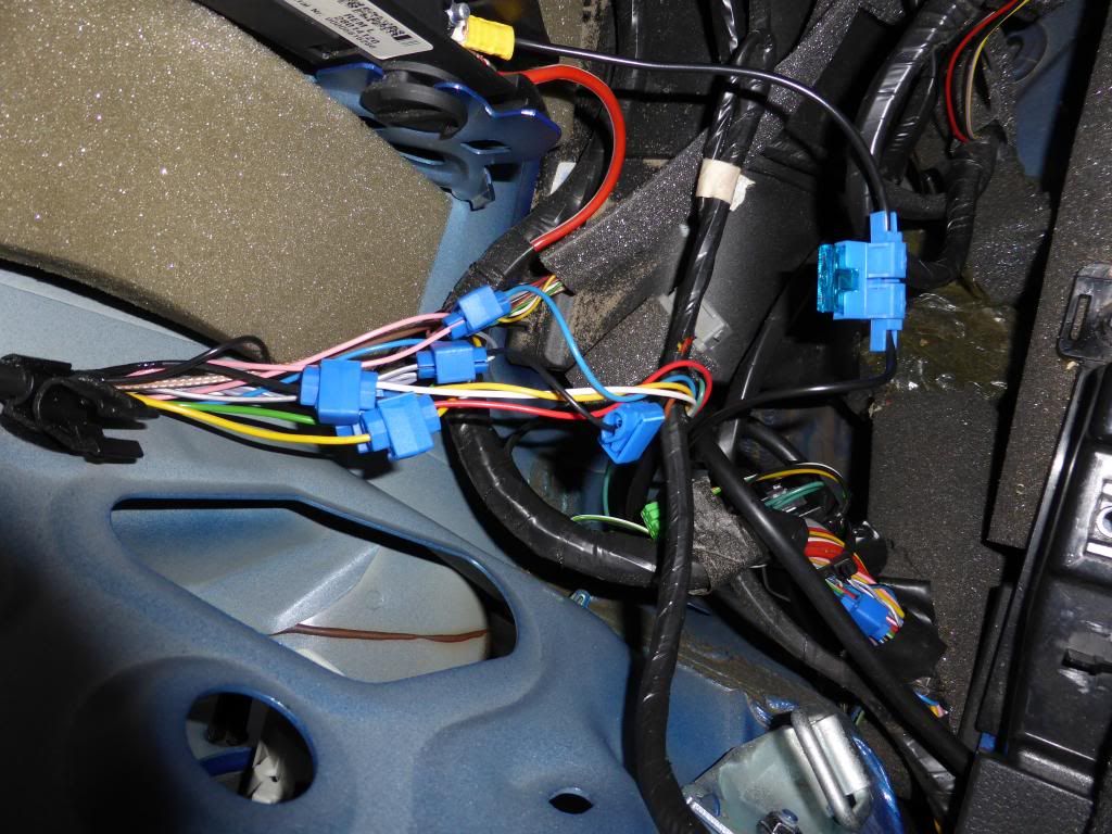
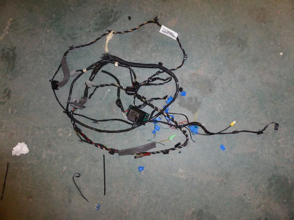
Then into the bin.
-
The Following User Says Thank You to Harvey For This Useful Post:
TenaciousC (Tuesday 12th July 2016)
-
Monday 18th July 2016, 11:56 #5Senior Member
Forced aspirations
- Join Date
- Jul 2008
- Location
- Warrington
- Posts
- 313
- Thanks
- 104
Thanked 41 Times in 25 PostsI persevered with my poor mans's relay unit and got to a working state in the end.
Some tips for anyone else:
- to get the wires from the battery and the off-side I had to undo the lower boot lip trim panel on the nearside. This means having to take off the top courtesy light panel, the nearside boot ceiling panel, the nearside D pillar and boot side wall. It's actually not too bad. Procedure is in Haynes
- Connected earth the point near battery and +ve to main fusebox connection
- Used 20A inline fuse to protect system.
- The colours to tap into are actually easy enough to find from the wiring diagrams in the Haynes manual. The light clusters are divided into 2. Upper is indicator, brake and reverse. Lower are running lights, and fog lights.
- All vampire connections can be made on the LHS clusters. I only needed to run a line over to the RHS for the indicator (my relay did not distinguish between left and right running lights).
- I used doubled sided padded tape to fix the 7way unit to the side of a plastic vent below fuse box. Same for buzzer.
- For testing, you can hear audible clicks from relay when a light comes on. Other than that, I used a multimeter at the tow socket to verify things.
Useful things to have before you start:
- Electric tools: wire stripper, snips, crimps, multimeter
- A selection of crimped spade connectors fittings
- Some automotive wire... 30A for power and earth, 5 A for all else
- Haynes manual for wiring diagrams
Last edited by TenaciousC; Monday 18th July 2016 at 12:05.
-
The Following User Says Thank You to TenaciousC For This Useful Post:
jamesy12345 (Monday 18th July 2016)

 Reply With Quote
 Danger Mouse
 Medium-sized-purple-one
 The Black Pearl [Necklace]
 2005 Volvo S60r
 2005 Volvo V70R


Thread Information
Users Browsing this Thread
There are currently 1 users browsing this thread. (0 members and 1 guests)
 Posting Permissions

Bookmarks