


Hello all,
The side brake lights no longer work but the top brake light does.
The bulbs and fuses (after being replaced due to attaching a trailer blew one of the fuses) are OK.
When the brake pedal is pressed with no key in the ignition, I can here and feel a relay working at the Rear Electronic Control Module.
All of the relays are black so I cannot easily determine if the relay I have identified is the correct one (original is blue I believe).
Does anyone know if the RECM has names for each relay, as I will need to remove the rear left-hand luggage panel in order to gain access to the relay in question?
Also, if the relay is clicking then this indicators that it is OK, correct? If yes, then what else could have caused this problem?
Results 1 to 20 of 21
Thread: Brake light issue v70 d5
-
Saturday 2nd November 2013, 16:46 #1Junior Member
 This user has no status
- Join Date
- Dec 2012
- Posts
- 18
- Thanks
- 13
Thanked 1 Time in 1 PostBrake light issue v70 d5
-
Saturday 2nd November 2013, 17:46 #2Member
This user has no status
- Join Date
- Oct 2013
- Location
- Blackpool
- Posts
- 81
- Thanks
- 1
Thanked 58 Times in 42 PostsDouble check fuse 3 and 14 in the REM as both of these feed the rear brake lights but have nothing to do with feeding power to the center brake light, if both fuses are OK you will need to pull the right rear trim panel out to get access to the REM, the brake light relay is idented RMI5 - Mike
-
The Following User Says Thank You to mikealder For This Useful Post:
LiamT4 (Tuesday 5th November 2013)
-
Monday 4th November 2013, 11:00 #3Junior Member
This user has no status
- Join Date
- Dec 2012
- Posts
- 18
- Thanks
- 13
Thanked 1 Time in 1 PostTks Mike.
I have checked all fuses in all three fuse boxes and they are all OK.
I have swapped MI4 with MI5, and my reverse lights still work but my stop lights do not.
I have also swapped SH2 with SH6, and my rear fog light still works but my stop lights do not.
All other tail lights work too.
-
Monday 4th November 2013, 14:37 #4Member
This user has no status
- Join Date
- Oct 2013
- Location
- Blackpool
- Posts
- 81
- Thanks
- 1
Thanked 58 Times in 42 PostsPut all the relays and shunts back where they should be then get to work with a Digital Voltmeter (DVM) if you don't have one they can be purchased from the likes of Maplins (Code UT30B for under a tenner).
Use the meter to look for the 12V feed on the relay socket RMI5 pin 5 of the relay socket with respect to chassis, you should have +12V on that pin all the time. Put the relay back in then move to next step assuming 12V was found on Pin 5 of the relay socket
Pull fuse 11D/14 and insert meter probe in to the fuse socket (terminal 1 which is the live pre-fuse side) connect other meter probe to chassis and get a helper to depress the brake pedal, if you get 12V here there is nothing wrong with the CEM/ REM and I would be looking for damage to the Green wire especially around splice 53/667 which you will find in the main wiring loom around the base of the left rear lower light assembly, it should have three green wires in it - Mike
-
The Following User Says Thank You to mikealder For This Useful Post:
LiamT4 (Tuesday 5th November 2013)
-
Monday 4th November 2013, 17:05 #5Senior Member
trying hard to look busy!
- Join Date
- Dec 2008
- Location
- Doncaster, South Yorkshire
- Posts
- 2,491
- Thanks
- 1,050
Thanked 579 Times in 486 PostsGreat advice there Mike. Have you checked connection at light unit isn't furred up?
It's a 5 Cylinder Orchestra!
R.I.P. Kyebosh (Alan) you're memory lives on!
-
Tuesday 5th November 2013, 18:21 #6Junior Member
This user has no status
- Join Date
- Dec 2012
- Posts
- 18
- Thanks
- 13
Thanked 1 Time in 1 PostTks Mike.
Socket 5 for MI5 does not give any voltage when the voltmeters negative probe touches the RECM's earth screw, regardless if the ignition is off or on all the way before ignition is initiated.
Does this mean that the RECM is defective, and if so, can it be fixed or must it be replaced?
-
Tuesday 5th November 2013, 18:33 #7Member
This user has no status
- Join Date
- Oct 2013
- Location
- Blackpool
- Posts
- 81
- Thanks
- 1
Thanked 58 Times in 42 PostsAssuming fuse 11D/3 is intact it does appear the REM is defective, this is a very costly item to replace and it you want to work around the issue you can fit another relay external to the REM with a bit of wiring added to get the brake lights working again, the main issue in doing this is the loss of bulb failure detection on the brake lights - Let me know if you want details on how to do this, it isn't difficult and should cost less than £10 in parts - Mike
-
The Following User Says Thank You to mikealder For This Useful Post:
LiamT4 (Tuesday 5th November 2013)
-
Tuesday 5th November 2013, 20:11 #8Junior Member
This user has no status
- Join Date
- Dec 2012
- Posts
- 18
- Thanks
- 13
Thanked 1 Time in 1 PostHello Mike,
Can you please let me know where fuse 11D/3 is located?
I am also interested in how to fit a different relay for the4 brake lights that you have mentioned.
-
Tuesday 5th November 2013, 20:18 #9Member
This user has no status
- Join Date
- Oct 2013
- Location
- Blackpool
- Posts
- 81
- Thanks
- 1
Thanked 58 Times in 42 Posts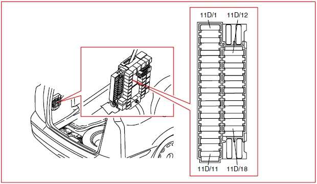
You can work out where 11D/3 is from the above picture, check that before we move on to fitting a new relay, check both sockets the fuse blade fits in to with the meter with respect to chassis and make sure the brake pedal is depressed while looking for a voltage on the meter - Mike
-
The Following User Says Thank You to mikealder For This Useful Post:
LiamT4 (Tuesday 5th November 2013)
-
Tuesday 5th November 2013, 20:31 #10Senior Member
VPCUK Car of the Year 2013
Jim
- Join Date
- Feb 2009
- Location
- Kangaroo land
- Posts
- 11,131
- Thanks
- 7,069
Thanked 5,282 Times in 3,549 Posts Originally Posted by mikealder
 Originally Posted by mikealder
Them above got to be the most useful first 4 posts from a member ive ever seen, quality Mr Alder Originally Posted by mikealder
Originally Posted by mikealder
Originally Posted by mikealder
Them above got to be the most useful first 4 posts from a member ive ever seen, quality Mr Alder Originally Posted by mikealder

T35, 556Nm/410lbft & 361BHP/317WHP
-
Tuesday 5th November 2013, 20:45 #11Beer Baron
Nice to have some power again.
- Join Date
- Jan 2010
- Location
- Leicester
- Posts
- 10,055
- Thanks
- 1,849
Thanked 2,466 Times in 1,996 PostsAgreed! Originally Posted by Jamest5r
"The problem with internet quotes, is that you don't know if they're real or not" - Abraham Lincoln
-
Tuesday 5th November 2013, 23:28 #12Senior Member
trying hard to look busy!
- Join Date
- Dec 2008
- Location
- Doncaster, South Yorkshire
- Posts
- 2,491
- Thanks
- 1,050
Thanked 579 Times in 486 PostsVery in depth for first posts. Welcome to VPCUK Originally Posted by LiamT4
It's a 5 Cylinder Orchestra!
R.I.P. Kyebosh (Alan) you're memory lives on!
-
Wednesday 6th November 2013, 11:10 #13Junior Member
This user has no status
- Join Date
- Dec 2012
- Posts
- 18
- Thanks
- 13
Thanked 1 Time in 1 PostTks again Mike.
That confirms that I did check the correct fuse, which is just F3 on my box, and it wasnt reading any voltage when the brake pedal was being pressed.
If no voltage is at that fuse nor at pin 5 of the relay, why does the relay still click when the brakes are applied?
I unclipped the REM and found that it has three green wires. One goes to F14, one to SH4 and the other to SH5. F14 isnt fitted (my Haynes manual also states that no fuse should be fitted. As you mentioned this fuse, can you please provide more details as to why one should be fitted and what its amps should be?), and those two shunts are not related to the brakes.
I can get the inner black part of the REM for around €40 - http://www.ebay.de/itm/Volvo-S60-S80...11206743625%26
I haven't found the REM's outer grey part yet though.
Do you know how to determine if the black or grey part is at fault, or will it be the black part as that has the circuit board inside it?
To replace the REM, I see that it will require the removal and fitting of many, many wires, so do you know if there is a special removal tool for them, as I obviously do not want to break any?
-
Wednesday 6th November 2013, 11:15 #14Senior Member
228k and still not broke it!
- Join Date
- Jul 2011
- Location
- Poole, Dorset
- Posts
- 23,213
- Thanks
- 6,548
Thanked 7,752 Times in 5,648 Posts Originally Posted by Jamest5r
Originally Posted by LiamT4
Reminds me of Harvey's first post. Pinned down and pretty much fixed an autobox problem with his first post. Originally Posted by jdavis
We should be nice to this lad lol, Welcome aboard Mr. Alder!19t, greens, 3" inlet, 3" downpipe with race cat, V70R catback, autotech map...
310.2bhp / 333ft/lb
2016 Swedish Day UK "Best Modified Swede"
SOLD
Got an old discovery now.
-
The Following User Says Thank You to M-R-P For This Useful Post:
Harvey (Wednesday 6th November 2013)
-
Wednesday 6th November 2013, 11:24 #15Senior Member
Keeping it looking stock
- Join Date
- Mar 2012
- Location
- Newton abbot, Devon
- Posts
- 5,567
- Thanks
- 920
Thanked 1,581 Times in 1,296 PostsI don't think you can just if a different one as the software will be wrong,it will need a trip to the dealer.
-
Wednesday 6th November 2013, 13:06 #16Senior Member
trying hard to look busy!
- Join Date
- Dec 2008
- Location
- Doncaster, South Yorkshire
- Posts
- 2,491
- Thanks
- 1,050
Thanked 579 Times in 486 Postsif it's pre facelift i think he may be ok without the dealer visit.
It's a 5 Cylinder Orchestra!
R.I.P. Kyebosh (Alan) you're memory lives on!
-
Wednesday 6th November 2013, 17:23 #17Senior Member
Keeping it looking stock
- Join Date
- Mar 2012
- Location
- Newton abbot, Devon
- Posts
- 5,567
- Thanks
- 920
Thanked 1,581 Times in 1,296 PostsWhat year is the car then.
-
Wednesday 6th November 2013, 17:58 #18Member
This user has no status
- Join Date
- Oct 2013
- Location
- Blackpool
- Posts
- 81
- Thanks
- 1
Thanked 58 Times in 42 PostsLets start with the wiring diagram and an explanation as to how the circuit works that I hope will make sense to you, you do indeed need the fuse 11D/14 installed as there is no way for power to pass to the rear outboard brake lights when this is missing - No idea why it is removed from your car and I would far rather trust the Volvo diagram than a generic style diagram in a Haynes book. 11D/14 should be rated at 7,5A.
First the diagram which I have colour coded to make it easier to follow in the text below:
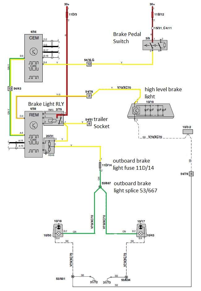
Lets start at top right with the fuse 11B/12 this feeds battery voltage to the brake pedal switch, with the pedal switch depressed the 12V travels through the yellow wire going through connector 54/3LG pin 12 before going to the CEM arriving on pin B4. The CEM then inverts this signal prior to feeding out a discrete signal to the REM on the green and yellow wire routing through connector 54/43 pin 13 which is under the left hand side of the rear seat base.
The REM now does two things with the 0V switched signal going in on A4, firstly it provides a +12V output on D4 which is a yellow and red wire this passes through the tailgate connector 54/78 pin 3 where it changes to a yellow wire routing to the center brake light. The other thing the REM does is to energise the brake light relay.
All the above is working on the O/Ps car which explains why you can hear the relay clicking when you operate the brake pedal.
From this point I will detail what should be happening:
+12V is fed through fuse 11D/3 which goes to the brake light relay, when this relay is energised it feeds power out on the yellow wires to the trailer socket 54/51 pin 4 and to the Shunt RSH6 which provides bulb failure detection for the brake light circuit, the yellow wire from the center of RSH6 feeds power to fuse 11D/14 (7,5 Amp rated). The output of fuse 11D/14 is a green wire feeding power to splice 53/667 which is in the main wiring look under the REM, the splice is a small black heat-shrink covered metal barrel containing three green wires. The two green wires then connect to the brake light bulbs on both sides of the car.
Try refitting a 7,5A fuse to 11D/14 then see if the brake lights work, if not take the REM off its mounting structure and have a good look at the rear of where the brake light relay is located, check the two yellow wires are still connected to the relay base and not damaged (as in burnt out from connecting the defective trailer) - Hope this helps.
Thanks for the welcome chaps, I will start a thread in the correct section about my own V70 when we get this little issue sorted out - Mike
-
The Following User Says Thank You to mikealder For This Useful Post:
v70d5 (Thursday 7th November 2013)
-
Thursday 7th November 2013, 11:16 #19Junior Member
This user has no status
- Join Date
- Dec 2012
- Posts
- 18
- Thanks
- 13
Thanked 1 Time in 1 PostHello Mike,
That was indeed a very good explanation. Adding a 7.5A fuse to F14 in the luggage compartment has rectified this issue.
This is embarrassing as I believe that I caused this situation when I was replacing blown fuses. As I didn’t have enough spare fuses, I checked the Haynes manual and as it said that F14 and some others were not used, it must have been one of a few that I used to replace the remaining blown fuses.
As it seems that Haynes manual's cannot be trusted, what is the best maintenance book to use for a 2003 V70 LHD?
-
Thursday 7th November 2013, 16:51 #20Member
This user has no status
- Join Date
- Oct 2013
- Location
- Blackpool
- Posts
- 81
- Thanks
- 1
Thanked 58 Times in 42 PostsThe Haynes isn't too bad for generic information but you will get better detail and tips for any pending jobs on the car by posting questions on the forum, I would never rely upon a Haynes wiring diagram, the Volvo ones are much better, grab a copy and save it to your PC from Here just make sure you pick the correct model and year, the diagrams aren't colour coded like the one I posted earlier but they do contain information about the colour of each wire just remember the abbreviation's used for each colour are in Swedish which can take a bit of getting used to. Originally Posted by v70d5
Glad to hear the car is fixed all the same - Mike
-
The Following User Says Thank You to mikealder For This Useful Post:
v70d5 (Friday 8th November 2013)

 Reply With Quote


 Bargemeister
 "THE BIG SWEED"
 2005 Volvo S60r
 2005 Volvo V70R
Thread Information
Users Browsing this Thread
There are currently 1 users browsing this thread. (0 members and 1 guests)
 Posting Permissions

Bookmarks