


 "The 5"
 Air Cav 850
Hi,
im thinking about the whole MBC thing, but i just want some more information about the turbo in general. im bad with the abreiviations so it would be good if we could write the words to?
what are the 3 air line connectors on this picture.
i believe the bottom one is where the compressor housing pressure gets sent to the boost controller (BCS?)
The top connector is for the actuator which controls the wastegate.
These 2 connectors are used for the manual boost controller?
so whats the 3rd connector and where does the other end of the vacuum hose go to?
thanks.
Results 1 to 17 of 17
Thread: Turbo Talk
-
Wednesday 6th October 2010, 12:28 #1Senior Member
 This user has no status
- Join Date
- Jun 2010
- Location
- N. Lincs/S.Yorks
- Posts
- 201
- Thanks
- 1
Thanked 60 Times in 27 PostsTurbo Talk
-
Wednesday 6th October 2010, 12:46 #2Senior Member
a 19t just isn't laggy enough
- Join Date
- Aug 2004
- Posts
- 19,785
- Thanks
- 4,216
Thanked 5,021 Times in 4,072 Poststhe 3rd one is the recirc valve, the other end of the pipe goes to the inlet manifold Originally Posted by manback


-
Wednesday 6th October 2010, 14:10 #3Senior Member
This user has no status
- Join Date
- Nov 2009
- Location
- Galashiels - Scottish Borders
- Posts
- 1,057
- Thanks
- 98
Thanked 238 Times in 172 PostsIf you are thinking of going down the MBC route, I can recommend it. I had been sceptical of them but after much reading, bought one and fitted it to my S70 T5 the other week. It made a massive difference, and is still running safe and consistent boost, with no spikes, and with the BCS still plugged in electrically, so as not to throw any warning lights.
Back in Black (T4)
-
Wednesday 6th October 2010, 18:41 #4Senior Member
This user has no status
- Join Date
- Jun 2010
- Location
- N. Lincs/S.Yorks
- Posts
- 201
- Thanks
- 1
Thanked 60 Times in 27 PostsAnd what's that for then? Originally Posted by p fandango
-
Wednesday 6th October 2010, 19:07 #5Senior Member
a 19t just isn't laggy enough
- Join Date
- Aug 2004
- Posts
- 19,785
- Thanks
- 4,216
Thanked 5,021 Times in 4,072 Postsit does exactly the same thing as a dump valve. When you back off the throttle ie to change gear the turbo still continues to spin because of how well there balanced, the recirc valve opens & lets this unwanted boost out. A recirc valve puts it back into the system while a dump valve lets it out to the atmosphere Originally Posted by manback
Last edited by p fandango; Wednesday 6th October 2010 at 19:11.
-
The Following User Says Thank You to p fandango For This Useful Post:
Volvostorm (Wednesday 6th October 2010)
-
Wednesday 6th October 2010, 19:08 #6Senior Member
Blah Blah Blah!
- Join Date
- Nov 2008
- Location
- Condover
- Posts
- 4,124
- Thanks
- 92
Thanked 917 Times in 807 Posts
 It does the same job as a dump valve, it releases boost pressure when the throttle s closed, i.e changing gear. Originally Posted by manback
It vents into the exhaust, while a dump valve vent to open, yes, you need it running a MBC

-
Wednesday 6th October 2010, 19:15 #7Senior Member
This user has no status
- Join Date
- Jun 2010
- Location
- N. Lincs/S.Yorks
- Posts
- 201
- Thanks
- 1
Thanked 60 Times in 27 PostsNow I'm confused. Mr. Fandango says it goes to the inlet manifold and you say it goes to the exhaust. Either way how does it know when to go off? Originally Posted by Pault5estate
And surly its not going to the inlet
Manifold because that's where all the compressed air goes anyway.?Last edited by manback; Wednesday 6th October 2010 at 19:21.
-
Wednesday 6th October 2010, 19:24 #8Senior Member
Blah Blah Blah!
- Join Date
- Nov 2008
- Location
- Condover
- Posts
- 4,124
- Thanks
- 92
Thanked 917 Times in 807 Posts
Sorry, my mistake, that turbo does vent into the inlet,I was thinking of the wastgate

As for the valve, this might help explain things: http://en.wikipedia.org/wiki/Blowoff_valve
-
Wednesday 6th October 2010, 19:31 #9Senior Member
a 19t just isn't laggy enough
- Join Date
- Aug 2004
- Posts
- 19,785
- Thanks
- 4,216
Thanked 5,021 Times in 4,072 Poststhe other end of the small pipe which connects to the recirc valve goes to the inlet manifold, when on power the positive manifold pressure pushes against the boost in the recirc valve keeping it closed. Once you let off the throttle the pressure drops in the manifold so there is nothing fighting the positive (wasted) boost pressure so it escapes Originally Posted by manback
-
Wednesday 6th October 2010, 21:31 #10Senior Member
This user has no status
- Join Date
- Feb 2005
- Posts
- 3,111
- Thanks
- 201
Thanked 528 Times in 448 PostsI thought the recirc valve operated via vacuum pressure myself. When you close the throttle sharply (ie to change gear) the turbo is still spinning and producing boost but that boost is now hitting a closed throttle butterfly threatening to stall the turbo. When the throttle is closed you induce a vacuum in the intake manifold (caused by the engine effectively 'sucking' against a closed throttle butterfly). The recirc valve is connected to the inlet manifold by a rubber tube and the vacuum induced in the manifold at closed throttle pulls the diaphragm in the recirc valve back against it's pressure spring which uncovers a bypass port allowing the boost pressure to escape into the intake piping (the unpressurized pipe between the maf and the turbo inlet). All this happens in 10ths of a second of course.
Old Car: 855 T5 in Grey and rust (dead and gone, well, most of it !
Missus' ride: Citroen C4 coupe 1.6 HDi,
Modifications: Nowt.....yet !
Daily driver: 855 R in Black,
Currently nursing a blown head gasket, new engine on its way !
Recent addition: Freshly imported Honda Stepwagon,
Slowly turning into a camper van !
-
Wednesday 6th October 2010, 22:28 #11Senior Member
This user has no status
- Join Date
- Jun 2010
- Location
- N. Lincs/S.Yorks
- Posts
- 201
- Thanks
- 1
Thanked 60 Times in 27 PostsGood info. Originally Posted by nobananas
If I remember right. There are 3 air pipes going to the unpressurised pipe. One at the top connects to the bcs. One connects to the oil breather system. I though the third one was the heated one that goes round the spark plugs on the engine cover/ rocker cover. And back to the pressure/vac tree between the idle contold valve and throttle body. So I don't see how pressure gets there unless it's always got a little bleed off!
-
Wednesday 6th October 2010, 23:20 #12Senior Member
This user has no status
- Join Date
- Feb 2005
- Posts
- 3,111
- Thanks
- 201
Thanked 528 Times in 448 PostsI don't quite understand which ones you are talking about ! The boost control solonoid will have 3 pipes to it. One from the turbine housing (compressor side) to the BCS then one from the BCS to the wastegate. The third pipe from the BCS simply vents into the intake pipe. On simple systems (mainly diesels) the turbine housing pipe is connected directly to the wastegate so as the boost in the turbo rises to it's required level the wastegate begins to open, this allows the exhaust gases to partially bypass the exhaust turbine which prevents the turbo from spinning any faster and the boost level stabilizes. On older diesels this was all you needed and the boost level was set by the strength of the spring in the wastegate but on vehicles requiring more accurate control of boost levels a BCS is plumbed in between the turbine housing and the wastegate and is controled by the ecu and it's this that helps more accurately to control the boost levels. There was a useful diagram floating about on here for a while but I can't find it ! Originally Posted by manback
Old Car: 855 T5 in Grey and rust (dead and gone, well, most of it !
Missus' ride: Citroen C4 coupe 1.6 HDi,
Modifications: Nowt.....yet !
Daily driver: 855 R in Black,
Currently nursing a blown head gasket, new engine on its way !
Recent addition: Freshly imported Honda Stepwagon,
Slowly turning into a camper van !
-
Wednesday 6th October 2010, 23:35 #13Senior Member
This user has no status
- Join Date
- Feb 2005
- Posts
- 3,111
- Thanks
- 201
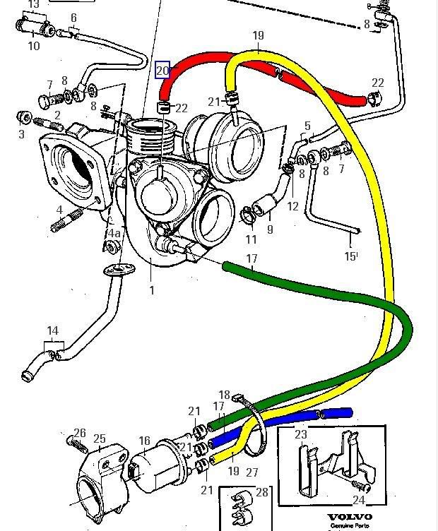
Thanked 528 Times in 448 PostsRight found the diagram, don't know who first put this up but whoever it was ta muchly !
You can see the green pipe coming from the compressor turbine housing going to the BCS, then the yellow pipe going from the BCS to the wastegate, the blue pipe is the vent to the intake near the air filter. The red pipe goes to the re-circ valve which will be connected at the other end to the inlet manifold or vac tree.
 Old Car: 855 T5 in Grey and rust (dead and gone, well, most of it !
Missus' ride: Citroen C4 coupe 1.6 HDi,
Modifications: Nowt.....yet !
Daily driver: 855 R in Black,
Currently nursing a blown head gasket, new engine on its way !
Recent addition: Freshly imported Honda Stepwagon,
Slowly turning into a camper van !
-
-
Tuesday 12th October 2010, 18:42 #14Senior Member
This user has no status
- Join Date
- Jun 2010
- Location
- N. Lincs/S.Yorks
- Posts
- 201
- Thanks
- 1
Thanked 60 Times in 27 PostsHi again, MBC arrived today.
 I fitted the big bit but am left with a smaller bit below.

I went for a test drive and the car felt much the same. So I turned it up abut and the boost never went above 5psi. So I turned it some more and it was avaunt just below 5psi. I don't suppose the mbcnworks the wrong way?
-
Tuesday 12th October 2010, 19:01 #15Whiny Old Git
Aching bones :(
- Join Date
- Aug 2009
- Location
- Shrewsbury
- Posts
- 9,069
- Thanks
- 4,385
Thanked 4,999 Times in 3,015 Postswhat you have there is a bleed valve (which is fine) you put the "T" into the pipe from the turbo to the wastegate (with the arrow pointing towards the wastegate) then a pipe ftom the other outlet on the "T" upto the bottom outlet on the bleed valve, leave the top outlet of the bleed valve open.
EDIT: just noticed it has an arrow on the bottom outlet of the bleed valve, so I'm actually not sure nowLast edited by claymore; Tuesday 12th October 2010 at 19:13.
PIC][/SIGPIC]
aaaaaaaaaaaaaaaaaaaaaaaaa
aaaaaaaaaaaaaaaaaaaaaaaaaaaaaaaaaaaaaaaaaaaaa aaaaaa
Facebook^^^^^^^^^^^^^^^^ Old T-5 Kompressor Thread^^^^^^^^^^^^^^^ New TT-10 Kompressor Thread
-
Tuesday 12th October 2010, 20:05 #16Senior Member
This user has no status
- Join Date
- Jun 2010
- Location
- N. Lincs/S.Yorks
- Posts
- 201
- Thanks
- 1
Thanked 60 Times in 27 PostsSo wha your saying is that the t piece should go In line between the Compressor housing and wastegate actuator. The 3rd conector should then go to the bleed valve. The 2nd conector on the bleed valve should be open to air. This would mean the more the valve is open the more air would vent and thus more presure would be required to open the wastegate????
-
Tuesday 12th October 2010, 20:41 #17Whiny Old Git
Aching bones :(
- Join Date
- Aug 2009
- Location
- Shrewsbury
- Posts
- 9,069
- Thanks
- 4,385
Thanked 4,999 Times in 3,015 PostsBingo
PIC][/SIGPIC]
aaaaaaaaaaaaaaaaaaaaaaaaa
aaaaaaaaaaaaaaaaaaaaaaaaaaaaaaaaaaaaaaaaaaaaa aaaaaa
Facebook^^^^^^^^^^^^^^^^ Old T-5 Kompressor Thread^^^^^^^^^^^^^^^ New TT-10 Kompressor Thread


 Reply With Quote
 BT
BT Meshashmitt


 1996 Volvo 850 T5
Thread Information
Users Browsing this Thread
There are currently 1 users browsing this thread. (0 members and 1 guests)
 Posting Permissions
vpcuk.org: A discussion forum for performance Volvo owners and enthusiasts.

Bookmarks