


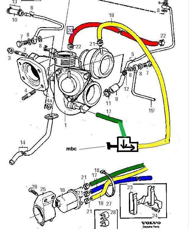
i just fitted my mbc. then after alot of ££££lin about decided i didnt like it and changerd back. but when i took the pipes off the solanoid to put them on mbc i noticed that the pipe where the opasit way round to this diagram.
mine had the green pipe coming from the turbo to the bottom hole in the solanoid and the yellow pipe coming from what i think is the wast gate toing to the top hole in the solanoid. the car has been working fine like this since i got it. should it be the other way round?
dont mind the changes i made to the pic was for my own use
Results 1 to 20 of 42
Thread: mbc
-
Monday 1st December 2008, 12:46 #1Senior Member
 This user has no status
- Join Date
- Jul 2008
- Location
- dunstable
- Posts
- 1,097
- Thanks
- 10
Thanked 46 Times in 44 Postsmbc

-
Monday 1st December 2008, 16:28 #2Suspended
This user has no status
- Join Date
- Oct 2008
- Location
- seaside
- Posts
- 388
- Thanks
- 32
Thanked 29 Times in 26 Postshmm i'm not too sure mate, altho thinking about i think my yellow one maybe on top also, will check tomorrow for you.
-
Monday 1st December 2008, 16:50 #3Senior Member
OH DEAR
- Join Date
- Jul 2008
- Location
- barnsley s.yorkshire
- Posts
- 12,470
- Thanks
- 2,138
Thanked 3,711 Times in 2,752 Postson the 850 bcs should be in this order also it has colour marking on it
TOP YELLOW= acuator
MIDDLE BLUE= air pipe
BOTTOM RED= turbo
-
Monday 1st December 2008, 16:58 #4Suspended
This user has no status
- Join Date
- Oct 2008
- Location
- seaside
- Posts
- 388
- Thanks
- 32
Thanked 29 Times in 26 Postsso assuming that diagram is from a later t5? ME7?
-
Monday 1st December 2008, 17:00 #5Senior Member
This user has no status
- Join Date
- Jul 2008
- Location
- dunstable
- Posts
- 1,097
- Thanks
- 10
Thanked 46 Times in 44 Postsin that diagram where i have added the mbc. have i added it right? is that the right way for the mbc to be or have i got it the rong way round?
-
Monday 1st December 2008, 17:03 #6Senior Member
OH DEAR
- Join Date
- Jul 2008
- Location
- barnsley s.yorkshire
- Posts
- 12,470
- Thanks
- 2,138
Thanked 3,711 Times in 2,752 Postsit says it all there if you have time 2mrw have a look at your bcs and make sure the right pipes are leading to the right colours Originally Posted by t5 pete

-
Monday 1st December 2008, 17:05 #7Senior Member
OH DEAR
- Join Date
- Jul 2008
- Location
- barnsley s.yorkshire
- Posts
- 12,470
- Thanks
- 2,138
Thanked 3,711 Times in 2,752 PostsI would think it is a diagram from the me7 due to the colours being different to the 850 diagram and also the location of the red pipe its white on the 850 diagram and come from the other side of the turbo from the recirc valve Originally Posted by 850twr
-
Monday 1st December 2008, 17:11 #8Senior Member
This user has no status
- Join Date
- Jul 2008
- Location
- dunstable
- Posts
- 1,097
- Thanks
- 10
Thanked 46 Times in 44 Postsyeah thats exactly the way mine is. in the diagram at the top have i fitted the mbc right in the pic? Originally Posted by t5 pete
-
Monday 1st December 2008, 17:15 #9Senior Member
OH DEAR
- Join Date
- Jul 2008
- Location
- barnsley s.yorkshire
- Posts
- 12,470
- Thanks
- 2,138
Thanked 3,711 Times in 2,752 Postsi have never fitted a mbc but it looks right to me as there the main two for the boost
-
Monday 1st December 2008, 17:17 #10Senior Member
This user has no status
- Join Date
- Jul 2008
- Location
- dunstable
- Posts
- 1,097
- Thanks
- 10
Thanked 46 Times in 44 Postsyeah i no they the right pipes but want to no if the mbc is the right way round. Originally Posted by t5 pete
-
Monday 1st December 2008, 17:26 #11Senior Member
This user has no status
- Join Date
- Sep 2006
- Posts
- 645
- Thanks
- 28
Thanked 115 Times in 99 Poststhere is a way to figure out if the mbc is the right way round or not but i've never been arsed to pay attention.
i've always just put it on and then if i find that any adjustments to the mbc make no difference to boost, switch it round the other way. simple.
if you've put it back the wrong way round i'd assume you'll probably run actuator pressure(not the same as boost pressure) so probably 3-6psi.
-
Monday 1st December 2008, 20:29 #12Senior Member
This user has no status
- Join Date
- Aug 2008
- Location
- rotherham s.yorkshire
- Posts
- 576
- Thanks
- 231
Thanked 59 Times in 55 Posts80110x, ive been using that diagram too when swapping my MBC and BCS. Originally Posted by t5 pete
so ive had -
top=turbo
middle=inlet pipe
bottom=actuator
what would happen (if anything) piping the BCS up like this, it ran ok 1991 retro alfa romeo 75
-
Monday 1st December 2008, 20:44 #13Senior Member
This user has no status
- Join Date
- Jul 2008
- Location
- dunstable
- Posts
- 1,097
- Thanks
- 10
Thanked 46 Times in 44 Postsso are you saying all along you had your bcs piped up rong? Originally Posted by nathT5
-
Monday 1st December 2008, 20:45 #14Senior Member
OH DEAR
- Join Date
- Jul 2008
- Location
- barnsley s.yorkshire
- Posts
- 12,470
- Thanks
- 2,138
Thanked 3,711 Times in 2,752 Postsyou would probley run the autuator pressure i geuss the way i have shown with the colours is a genuine diagram for a volvo 850 have a look at the colours on the 850 bcs its easy Originally Posted by nathT5
-
Monday 1st December 2008, 20:46 #15Senior Member
OH DEAR
- Join Date
- Jul 2008
- Location
- barnsley s.yorkshire
- Posts
- 12,470
- Thanks
- 2,138
Thanked 3,711 Times in 2,752 Postshahahaha ive only just figured out what 80110x means Originally Posted by nathT5
-
Monday 1st December 2008, 20:58 #16Senior Member
This user has no status
- Join Date
- Jul 2008
- Location
- dunstable
- Posts
- 1,097
- Thanks
- 10
Thanked 46 Times in 44 PostsLOL oh yeah i just sat and looked at it for a wile and then it came to me LOL Originally Posted by t5 pete
-
Monday 1st December 2008, 21:00 #17Senior Member
This user has no status
- Join Date
- Aug 2008
- Location
- rotherham s.yorkshire
- Posts
- 576
- Thanks
- 231
Thanked 59 Times in 55 Postsnot all the time but a good few weeks on and off. Originally Posted by stainesy
i keep changing from MBC to BCS every so often just to experiment.
ive always used the above diagram and it mainly ran good, boosting 3/4 up the gauge.1991 retro alfa romeo 75
-
Monday 1st December 2008, 21:02 #18Senior Member
This user has no status
- Join Date
- Aug 2008
- Location
- rotherham s.yorkshire
- Posts
- 576
- Thanks
- 231
Thanked 59 Times in 55 Posts Originally Posted by stainesy
its how i swear without writing the word, clever innit? Originally Posted by t5 pete
 1991 retro alfa romeo 75
-
Monday 1st December 2008, 21:18 #19Senior Member
This user has no status
- Join Date
- Jul 2008
- Location
- dunstable
- Posts
- 1,097
- Thanks
- 10
Thanked 46 Times in 44 Postsiv noticed that on my boost gauge when the engine is turned off the needle sits at -2 psi rather than on the 0 mark. and on idle it sits at -20 psi. so does that mean that when mine reads say 9 psi its actuly at 10 psi? should it be sitting at the 0 when engine off?
-
Monday 1st December 2008, 21:19 #20Senior Member
OH DEAR
- Join Date
- Jul 2008
- Location
- barnsley s.yorkshire
- Posts
- 12,470
- Thanks
- 2,138
Thanked 3,711 Times in 2,752 PostsIts probley just where the gauge settles at

 Reply With Quote
Thread Information
Users Browsing this Thread
There are currently 1 users browsing this thread. (0 members and 1 guests)
 Posting Permissions

Bookmarks